
Source wirepartelia55.z19.web.core.windows.net
The motherboard front panel pins are the small, tiny connectors in the front part of your computer's motherboard. Without these pins, your computer will not function properly or may not work at all. These pins are essential in establishing the communication between the motherboard and the external peripherals, such as the power button, reset button, LED lights, and USB ports.
Most PC builders do not realize the importance of the motherboard front panel pins, but they play a crucial role in providing an efficient and smooth-running computer system. Through these pins, you can customize the function of your computer by connecting different ports depending on your preference. It is also practical for those who want to control the system's power and performance or even shut it down in case of an emergency.
With today's technological advancements, most modern motherboards have simplified the installation of the front panel pins. These connectors are usually color-coded and help users plug and disconnect the wire connectors quickly. However, connecting them incorrectly may have detrimental effects on your computer, such as short circuits, voltage changes, overheating, and other issues, risking the motherboard's lifespan.
In conclusion, motherboard front panel pins are crucial to establish communication between the motherboard and the peripherals. These unassuming pins hold a vital role in creating an efficient computer system and customizing its function. Whether you are building your own custom PC or upgrading an existing one, understanding the motherboard front panel pins should be one of your top priorities.
Understanding Front Panel Pins of a Motherboard
A motherboard is a printed circuit board that serves as a foundation for a computer. On this board, there are various connectors and components that act as ports for the different components of a computer, making them function harmoniously. One of the most important parts of a motherboard is the front panel connector. In this article, we are going to discuss everything related to the motherboard front panel pins, their function, and how they work.
The Anatomy of Motherboard Front Panel Pins
The front panel pins on a motherboard are a small section on the bottom right part of the board. These pins are classified according to their function, which determines how they operate. Here are the different types of front panel pins that you can find on a motherboard:
| Connector | Pin name | Description |
|---|---|---|
| Power | Power On/Off | This connector operates the computer's power switch. |
| Power | Reset Switch | This connector resets the computer when pressed. |
| Power | Power LED (+) | The power LED connector indicates that the computer is turned on. |
| Power | Power LED (-) | The power LED (-) connector works in tandem with the power LED (+) connector to indicate that the computer is turned on. |
| Power | Hard Drive LED (+) | The hard drive LED (+) connector illuminates when there is hard drive activity. |
| Power | Hard Drive LED (-) | The hard drive LED (-) connector works in conjunction with the hard drive LED (+) connector to illuminate when there is hard drive activity. |
| Audio | Audio In | The audio in connector is where an audio device is connected to the motherboard. |
| Audio | Audio Out | The audio out connector is where an audio device is connected to the motherboard. |
| Audio | Mic In | The mic in connector is where a microphone is plugged in. |
The Functions of Motherboard Front Panel Pins
As stated earlier, the motherboard front panel pins have different functions that enable various parts of a computer to continue operating. As we delve deeper into these functions, it is essential to note that every connector name ends with a (+) or (-) or the complete name of that connector, so it's essential to watch out for that. The following are the Pin functions of the motherboard front panel pins:
| Pin Function | Description |
|---|---|
| Power On/Off | The Power On/Off button works to turn on or off a computer. When the button is pressed, it sends a signal to the motherboard, which, in turn, switches the computer on or off. |
| Reset Switch | The reset button works to reset the computer in the event of a glitch or when a computer program stops responding. |
| Power LED (+) | The Power LED (+) illuminates when the computer is turned on, indicating that the computer is working. |
| Power LED (-) | The Power LED (-) works with the Power LED (+) connector to indicate that the computer is functioning. |
| Hard Drive LED (+) | The Hard Drive LED (+) illuminates when the hard drive is operational, indicating that there is hard drive activity. |
| Hard Drive LED (-) | The Hard Drive LED (-) works with the Hard Drive LED (+) connector to illuminate when there is hard drive activity. |
| Audio In | The Audio In connector is where an audio device such as speakers is plugged in to receive audio signals. |
| Audio Out | The Audio Out connector is where the audio device such as speakers is plugged in to deliver audio signals. |
| Mic In | The Mic In connector is where a microphone is plugged in to record and transmit audio signals. |
The Importance of Front Panel Pins on a Motherboard
The Motherboard Front Panel Pins are essential components of a computer, and, without them, a computer wouldn't function to its full capacity. These pins enable the computer to start up, signaling the user that the computer is working correctly using the Power LED (+) connector. The reset button is crucial in resetting the computer after a glitch or an error, while the hard drive LED (+) and (-) connectors are essential in indicating when there is hard drive activity.
The Audio In, Audio Out, and Mic In connectors, on the other hand, are essential in receiving and transmitting audio signals, making them ideal for multimedia purposes utilizing audio devices such as speakers and microphones.
Conclusion
The motherboard front panel pins are necessary components of a computer, and without them, a computer wouldn't function to its full capacity. From turning on the system to providing audio and visual feedback, these connectors make it possible to communicate with a computer and achieve all the demands of the user.
For more information on motherboards, please visit Wikipedia.
Types of Front Panel Connectors on Motherboard
The front panel of the motherboard is where the user interacts with the computer, allowing a means of using power buttons, reset buttons, audio jacks, and USB ports. These front panel connectors are vital in ensuring the proper functioning of the motherboard. This article will discuss the different types of front panel connectors found on the motherboard and their uses.
1. Power Button Connector
The power button connector is a two-pin connector that connects directly to the power button present on the front of the computer case. When this button is pressed, the motherboard receives the signal to power up the computer. This connector is one of the most important front panel connectors.
2. Reset Button Connector
The reset button connector is a two-pin connector that also connects to a button on the front panel of the computer case. This button is used to reset the computer to its default settings in case of a malfunction or to exit an unresponsive program. The reset button is usually used only when a hard reset is required, and all current data should be saved before pressing this button.
Note: There are usually different connectors for each of these buttons as they serve different functions, but they are often found adjacent to each other on the motherboard.
3. HDD LED Connector
The HDD LED (Hard Drive Disk Light Emitting Diode) connector is a two-pin connector that connects to an LED light located on the front of the computer case. The HDD LED light indicates the activity of the hard drive by lighting up when data is read from or written to the hard drive.
4. Power LED Connector
The Power LED connector is a two-pin connector that connects to another LED light present on the front of the computer case. When the computer is powered on, this LED will light up, indicating that the computer is turned on.
5. Audio Connector:
The audio connector is a multi-pin jack that is found on the front panel of the motherboard. These jacks are used to connect headphones, speakers, or microphones to the computer. Depending on the motherboard, there may be separate connectors for each of these devices or a single connector capable of supporting all three functions.
6. USB Connector:
USB (Universal Serial Bus) connectors are the most commonly used connectors in a computer. These jacks allow the user to connect various external devices such as mouse, keyboard, external hard drive, cell phones, tablet, etc. The motherboard usually has multiple USB connectors, which are located on the rear of the computer and on the front panel of the computer case.
Summary
In conclusion, the front panel connectors of the motherboard play a crucial role in the functioning of the computer. Understanding the different types of front panel connectors and their functions is essential for everyone interested in building, repairing or understanding any computer system.
The table below summarizes the specifications of the front panel connectors.
| Connector | Type | Number of Pins | Function |
|---|---|---|---|
| Power Button Connector | Two-pin | 2 | Turns the computer on |
| Reset Button Connector | Two-pin | 2 | Resets the computer |
| HDD LED Connector | Two-pin | 2 | Displays HDD activity |
| Power LED Connector | Two-pin | 2 | Displays power on/off status |
| Audio Connector | Multi-pin | Multiple | Connects headphones, speakers, or microphones |
| USB Connector | Multi-pin | Multiple | Connects USB devices |
For more information about motherboard front panel pins, please visit https://en.wikipedia.org/wiki/Motherboard#Front_panel_connectors.
Pin layout and configuration of motherboard front panel
When assembling a computer, one crucial step is connecting the motherboard front panel pins to the corresponding connectors on the case. This step ensures the proper functioning of the computer's power and reset buttons, front audio and USB ports, and other front panel features. In this article, we will discuss the pin layout and configuration of motherboard front panel in detail.
The pin layout of motherboard front panel
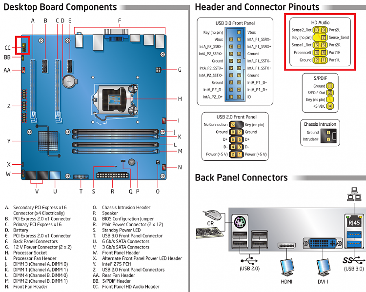
The motherboard front panel connector is located on the bottom-right corner of the motherboard, known as the front panel header. It consists of a block of pins that connect to the corresponding pins on the case's front panel cables. The pin layout varies depending on the motherboard model and manufacturer.
On most motherboards, the front panel header has pins for power switch, reset switch, hard drive LED, power LED, and speaker. Some motherboards may also include pins for additional features, such as front USB ports and front audio jacks.
The pins are often labeled or color-coded for easy identification. However, in cases where the pins are not labeled, the motherboard manual can provide the necessary information on the pin layout.
Below is an example of the pin layout for a standard front panel header:
| Pin | Signal |
|---|---|
| 1 | Power LED (+) |
| 2 | Power LED (-) |
| 3 | Power Switch |
| 4 | Reset Switch |
| 5 | Hard Drive LED (+) |
| 6 | Hard Drive LED (-) |
| 7 | Ground |
| 8 | Speaker |
The configuration of motherboard front panel
After identifying the pin layout, the next step is to connect the case's front panel cables to the corresponding pins on the motherboard's front panel header. The configuration involves attaching the correct cables to the correct pins based on the pin layout.
Most front panel cables are labeled on one end to indicate their function. For instance, the power switch cable is typically labeled "PWR_SW" or "POWER SW." The reset switch cable is typically labeled "RESET SW," and the hard drive LED cable is labeled "HDD LED." The power LED cable may have additional labels, such as "PWR LED" and "PLED."
Once the correct cables have been identified, connect them to the corresponding pins on the motherboard's front panel header. For example, the power switch cable should be attached to the pins labeled "Power Switch," while the hard drive LED cable should be attached to the "Hard Drive LED" pins. The positive and negative pins on the power LED cable should be attached to the corresponding pins labeled "Power LED (+)" and "Power LED (-)."
It is essential to ensure that the cables are attached correctly to avoid damaging the motherboard or the computer. Incorrect connections can cause the computer to fail to boot, cause short circuits or trigger other problems.
In summary, the correct configuration of motherboard front panel involves attaching the correct cables to their corresponding pins on the front panel header. This configuration follows the pin layout of the motherboard, which varies depending on the motherboard model and manufacturer.
For more information about motherboard front panel pins, you can check out this wikipedia article: https://en.wikipedia.org/wiki/Front_panel#Motherboard_header.
For a better understanding on how to connect your front panel pins to your motherboard, check out this guide on Best of Motherboard.
Common functions of motherboard front panel pins
Motherboard front panel pins are important components that are used to connect the computer's front panel to the motherboard. Front panel pins are also sometimes referred to as front panel headers, front panel connectors, or front panel cables. There are different types of front panel pins found on motherboards, and each has its specific functions. In this article, we will discuss the common functions of motherboard front panel pins.
Power switch pins
One of the most important functions of motherboard front panel pins is to connect the power switch from the computer case to the motherboard. The power switch pins can be identified on the motherboard by looking for the labels “PWR_SW” or “POWER SW.” When the power switch is pressed, it sends an electrical signal that turns on the computer's power supply. When the power supply receives this signal, it sends power to the rest of the computer components and boots up the computer.
Reset switch pins
Another function of the front panel pins is to connect the reset switch from the computer case to the motherboard. The reset switch pins are usually labeled “RESET SW” or “RST_SW” on the motherboard. The reset switch is used to restart the computer in case it freezes or becomes unresponsive. When the reset switch is pressed, it sends an electrical signal to the motherboard, which instructs it to restart the computer.
Hard drive LED pins
Hard drive LED pins connect the hard drive activity LED on the computer case to the motherboard. These pins are typically labeled “HDD_LED” or “HDLED” on the motherboard. When the hard drive is working, it sends an electrical signal to the hard drive LED pins, which cause the LED light on the computer case to flash. This blinking light indicates that the hard drive is being accessed.
Power LED pins
The power LED pins connect the power LED light on the computer case to the motherboard. These pins are typically labeled “PWR_LED” or “POWER LED” on the motherboard. The power LED light indicates whether the computer is turned on or off. When the computer is turned on, the power LED light glows, and when the computer is turned off, the power LED light turns off as well.
Speaker pins
The speaker pins connect the internal speaker on the computer case to the motherboard. These pins are typically labeled “SPK” or “SPEAKER” on the motherboard. The speaker is used to provide audio feedback during the boot-up process. If there are any errors or issues with the computer, the speaker will produce a series of beeps to alert the user.
USB pins
Some motherboards also have front panel USB pins that allow users to connect USB devices to the computer's front panel. These pins are typically labeled “USB” on the motherboard. With front panel USB pins, users can easily connect USB devices to the computer without having to access the USB ports located at the back of the computer.
Other pins
In addition to the pins mentioned above, there may also be other front panel pins on the motherboard that have specific functions. For example, some motherboards may have pins that allow users to connect firewire ports or audio jacks to the computer's front panel.
In conclusion, motherboard front panel pins play an important role in connecting the computer's front panel to the motherboard. Front panel pins are used to connect various components such as the power switch, reset switch, hard drive LED, power LED, speaker, and USB pins. Understanding the different types of front panel pins on a motherboard can help users troubleshoot any issues and ensure that their computer is running efficiently.
LSI Keywords: Computer motherboard, Front panel pins, Power switch pins, Reset switch pins, Hard drive LED pins, Power LED pins, Speaker pins, USB pins.
External link: https://en.wikipedia.org/wiki/Motherboard
Troubleshooting issues with front panel pins
The front panel pins on a motherboard connect the computer case to the motherboard and are responsible for activating certain features such as the power button, reset button, and LED lights. However, issues with front panel pins can arise, causing the computer to malfunction. In this article, we will discuss some common troubleshooting issues with front panel pins and how to fix them.
1. No power or booting up issues
One of the most common issues with front panel pins is the failure of the motherboard to turn on or boot up. This issue can be caused by a faulty power switch or a misconfigured connection. To fix this issue, start by double-checking the connections between the motherboard and the front panel pins. If the connections seem fine, it may be worth checking the power switch itself by testing it with a multimeter.
2. LED lights not working
If the LED lights on your computer case are not working, it may be because of loose connections or a burned-out LED. To fix this issue, start by checking the connections between the LED light and the motherboard. If the connections seem fine, it may be worth testing the LED light using a multimeter to determine whether it is burned out. If it is, you can replace it easily with a new LED light.
3. Reset button not working
If the reset button on your computer case is not working, it may be because of loose connections or a problem with the switch itself. To fix this issue, start by inspecting the connections between the reset button and the motherboard. If the connections seem fine, test the switch itself using a multimeter or replace the switch with a new one.
4. Audio or USB ports not working
If the audio or USB ports on your computer case are not working, it may be because of misconfigured connections or driver issues. To fix this issue, start by checking the connections between the audio or USB ports and the motherboard. If the connections seem fine, check if the appropriate drivers are installed in the system. If it is not installed, reinstall the driver.
5. Bent or broken pins
Bent or broken pins in the front panel header can cause numerous issues, such as device malfunction and system instability. Check for bent or broken pins anytime you encounter issues with your front panel header. If you find any pins that are bent or broken, you should carefully straighten or replace it. It is essential not to use tools to bend the pins back into place. There are chances that it could break the pin completely, damaging the motherboard's PCB.
| Issue | Cause | Solution |
|---|---|---|
| No power or booting up issues | Faulty power switch or misconfigured connection | Check connections and test the switch with a multimeter |
| LED lights not working | Loose connection or burned-out LED | Check the connections and test the LED with a multimeter and replace the LED |
| Reset button not working | Loose connection or problem with the switch itself | Check connections and test the switch with a multimeter or replace the switch |
| Audio or USB ports not working | Misconfigured connections or driver issues | Check connections and reinstall the driver |
| Bent or broken pins | Bent or broken pins in the front panel header | Carefully straighten or replace the pin without using tools |
In conclusion, front panel pins are essential to the proper functioning of a computer, and issues with them can lead to a cascade of problems. However, by understanding the common issues with front panel pins and how to troubleshoot them, you can save time and money in the long run. So, be patient while troubleshooting and always double-check your connections.
External Link: Motherboard Front Panel Pins
Connecting and Configuring LEDs on Front Panel Pins
The front panel of a motherboard contains several pins that can be connected to internal devices such as LEDs, power switches, or reset buttons. LEDs are small lights that are used to indicate the status of a device or its components. In this article, we will discuss the process of connecting and configuring LEDs to the front panel pins of the motherboard.
Understanding LED Connections
Before connecting LEDs to the front panel pins of the motherboard, it is important to understand the different types of connections that may be required. LEDs are typically powered by a 2-pin connection that consists of a positive (+) and negative (-) wire. However, LEDs that come with more advanced features may require additional pins for functions such as dimming, color control, or synchronization.
The front panel pins on a motherboard are usually labeled in accordance with their function. For example, the pins for the power switch may be labeled as "PWR_SW" while the pins for the reset button may be labeled as "RESET". In the case of LEDs, the pins may be labeled as "HDD_LED" for the hard drive activity LED or "POWER_LED" for the power indicator LED.
Connecting LEDs to the Front Panel Pins
The process of connecting LEDs to the front panel pins of the motherboard is relatively simple. However, it is important to ensure that the wires are connected to the correct pins and that the polarity of the LED is correct. The following steps can be used to connect LEDs to the front panel pins of the motherboard:
- Ensure that the computer is turned off and unplugged from the power source.
- Locate the front panel pins on the motherboard. These pins are usually located near the bottom of the motherboard and are labeled according to their function.
- Identify the positive (+) and negative (-) wires of the LED. These wires are usually connected to the LED by a small connector or through soldering.
- Connect the positive (+) wire of the LED to the corresponding positive (+) pin on the front panel connector. This pin is usually labeled with a plus sign (+) and may be a different color than the other pins.
- Connect the negative (-) wire of the LED to the corresponding negative (-) pin on the front panel connector. This pin is usually labeled with a minus sign (-) or may be the ground pin.
- If the LED comes with additional pins, connect them according to the manufacturer's instructions.
- Repeat the process for any additional LEDs that need to be connected.
- Ensure that all connections are secure and that the wires are not touching each other or other components on the motherboard.
Configuring LED Settings in the BIOS
Once the LEDs are connected to the front panel pins of the motherboard, they can be configured in the BIOS settings. The BIOS is a software that is embedded in the motherboard and controls various hardware settings such as the boot sequence, clock speed, and power management. The following steps can be used to configure LED settings in the BIOS:
- Turn on the computer and press the key to enter the BIOS settings. The key to enter the BIOS varies depending on the motherboard manufacturer but is usually shown on the screen during the boot-up process.
- Locate the section for "Hardware Monitoring" or "System Status" in the BIOS settings. This section may be located in a different location depending on the motherboard model and manufacturer.
- Locate the option for "LEDs" or "Front Panel Indicators" in the Hardware Monitoring settings. This option may be labeled differently depending on the motherboard model and manufacturer.
- Select the option for "Enabled" to activate the LED indicators on the front panel.
- Configure any additional settings for the LEDs such as brightness, color, or synchronization. These settings may vary depending on the motherboard model and manufacturer.
- Save and exit the BIOS settings. The computer will restart and the LED indicators should now be active.
Connecting and configuring LEDs on the front panel pins of the motherboard is a simple process that can add visual indicators for the status of internal components to the computer. It is important to ensure that the connections are correct and that the LED polarity is correct to prevent damage to the motherboard or other components. With the correct configuration, the LEDs can provide valuable information on the status of the computer and its components.
External Link: Motherboard - Wikipedia
Modifying front panel pins for custom builds
The front panel of a computer case is where the power switch, reset button, audio jacks, and USB ports are located. These components are connected to the motherboard through a set of pins known as the motherboard front panel pins. The standard front panel pins of a motherboard are designed to work with a specific case and cannot be changed without modifying the pin layout. This article will explain how to modify the front panel pins to customize the case and motherboard connection for specific builds.
Understanding the basic layout of front panel pins
The front panel pins are typically located along the bottom edge of the motherboard and are labeled with small letters or numbers. There are two sets of pins: one for the power button, reset button, and LED lights, and another for the audio jacks and USB ports. Each pin has a specific function and connects to a corresponding component on the case.
Table 1: Basic layout of front panel pins
| Pin | Function |
|---|---|
| PWR | Power button |
| RST | Reset button |
| HDD LED | Hard drive activity LED |
| PWR LED | Power LED |
| SPK | Speaker |
| HD Audio | Audio jacks |
| USB | USB ports |
Modifying front panel pins for custom builds
If you want to modify the front panel pins for a custom build, you will need to locate the pinouts for your motherboard in the manual or online. Once you have the pinout diagram, you can customize the layout by swapping pins or adding additional components.
Table 2: Example of front panel pinout diagram
| Pin | Function | Description |
|---|---|---|
| 1 | PWR | Power button |
| 2 | GND | Ground |
| 3 | PWR LED- | Negative power LED |
| 4 | PWR LED+ | Positive power LED |
| 5 | RESET | Reset button |
| 6 | GND | Ground |
| 7 | HDD LED- | Negative HDD activity LED |
| 8 | HDD LED+ | Positive HDD activity LED |
For example, if you want to add more USB ports to your front panel, you can swap the pins for the reset button and USB ports. You will need to remove the reset button and connect the USB ports to the reset button pins. Alternatively, you could add a USB hub and connect it to the USB pins on the motherboard.
Another customization option is to add LEDs to your front panel. You can add additional LED lights by connecting them to the power LED pins on the motherboard. You can also customize the LED colors by using different colored LEDs or by modifying the wiring of the LEDs.
With some basic knowledge of front panel pins and a little bit of creativity, you can easily modify the front panel pins for custom builds.
Conclusion
Modifying the front panel pins of a motherboard can be a fun and rewarding experience for PC enthusiasts. With the right tools and knowledge, you can easily customize the front panel pins to fit your specific build. Whether you want to add more USB ports, LEDs, or other components, there are plenty of customization options available.
External link: https://en.wikipedia.org/wiki/Motherboard#Front_panel_connectors
FAQ and Conclusions
Motherboard front panel pins are the small connectors that bring connectivity to the external devices from the computer. They are fundamental parts of a PC and are responsible for power, reset, and operations control. However, the setup process can be tricky for some users. Here are ten frequently asked questions about motherboard front panel pins:
1. What is the Purpose of Motherboard Front Panel Pins?
Motherboard front panel pins are responsible for connectivity to external devices in a PC. They enable the power supply to power up the computer, enable the CPU's operation, and reset the computer to default settings when necessary.
2. What are the Most Common Front Panel Pin Configurations?
The most common front panel pin configurations are two-pin connectors F_Panel and PWR_BTN. F_Power connects the power supply, while PWR_REQ connects the power button to turn on the computer.
3. How Can I Find the Front Panel Pin on My Motherboard?
You can look up your motherboard manual if you know its model. The manual contains a detailed diagram that shows the location of your front panel pin connectors.
4. Can I Use Any Front Panel Connectors With My Motherboard?
No, you cannot. You need to use the front panel connectors that are compatible with your motherboard to avoid any damage and wrong connectivity.
5. What is the CPU Power Connector?
The CPU power connector is used for providing power to the processor. It is located near the CPU socket. The connector comes in four-pin and eight-pin variants.
6. What is the Difference Between Power Switch and Restart Button?
The power switch is used to turn on and off the computer, while the reset button is used to restart the computer when it freezes or crashes entirely.
7. How do I Connect the Front Panel Pins to My Motherboard?
To connect the front panel pins to your motherboard, you need to go very carefully and cautiously. Follow your motherboard manual to know your motherboard's layout and connector groupings.
8. What is a Jumper?
A jumper is a small plastic cap that connects two pins on a motherboard. It changes the functionality of the motherboard by altering the circuitry and acts as a logical gate.
9. Will My Computer Turn on Without Front Panel Pins?
No, your computer won’t turn on. Every removable device of the computer needs to be appropriately connected to work flawlessly.
10. What Could Happen if I Connect the Front Panel Pins Incorrectly?
Wrongly connected front panel pins can cause short circuits and damage to the motherboard and computer components. Hence it is recommended to carefully follow the diagram on the motherboard manual.
In conclusion, motherboard front panel pins are an essential component of a computer and need adequate handling to function accurately. Properly connecting them brings a myriad of benefits, including efficient system performance and effective troubleshooting processes. Follow the guidelines given in the motherboard manual to ensure that your computer functions correctly and safely. Happy building!


Post a Comment
Post a Comment